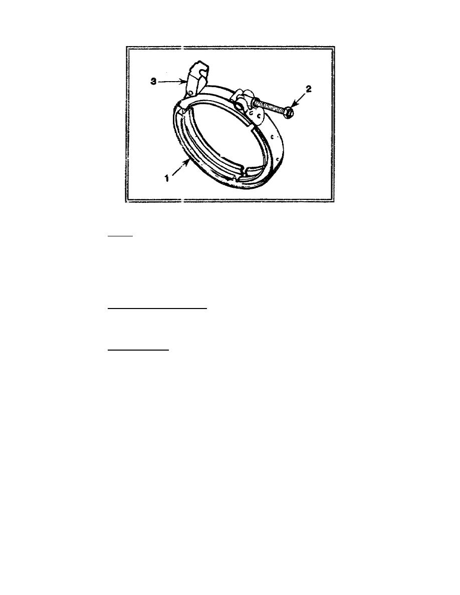
Figure 1-5. Nozzle clamp assembly
(5) Ignitor. The ignitor (Figure 1-6) is installed through the top of the engine tube just
behind the engine head. The ignitor provides the spark for the initial explosion of fuel and air in the
combustion chamber. Electrical power for the ignitor is drawn from the vehicle batteries. Successive
explosions occur when fresh fuel-air mixtures injected through the engine valve come into contact with
the hot gases inside the combustion chamber. The explosions of the pulse-jet engine occurs
approximately 60 times a second.
(6) Sensing element assembly. The sensing element assembly consists of a sensing
element, element clamps, and grommets. In the event of an engine head fire, the sensing element will
detect the heat from the fire and activate the fire alarm light on the control panel.
(b) Cover Assembly. The cover assembly mounts to the frame assembly in front of and
below the engine head. The cover assembly (Figure 1-7) contains a fuel pump motor (1), a fuel solenoid
valve (2), and an in-line fuel filter (3). The fuel pump motor draws fuel from the fuel cans, and the in-
line fuel filter removes dirt and other particles. The fuel solenoid valve regulates the flow of fuel into
the nozzle assembly. When the fuel pump is activated, it continuously draws fuel out of the fuel cans to
the fuel pump motor and returns it again to the fuel cans. Once the engine is started on the M54 Smoke
Generator, the fuel solenoid valve diverts part of the fuel to the nozzle assembly; the remaining fuel
returns to the fuel cans. The front face of the cover assembly (Figure 1-8) contains a plug connection for
the electrical power cable (1) and quick-disconnect coupling half connections for the fog oil hose (2),
the air hose (3), the fuel input hose (4), and the return hose (5). There is also a fuel check point (6) for
measuring the fuel pressure generated by the fuel pump motor.
CM3305
1-6


 Previous Page
