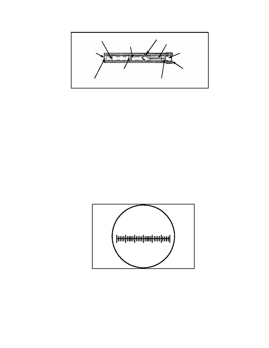
Calibrated scale
Indicating fiber
Support wire
Ionization chamber
Viewing end
Charging end
Objective lens
Protective cap
Eyepiece lens
Charging contact
Figure 2-2. Cross-Sectional View of the Dosimeter
2-4. Principles of Operation. The conducting system in the dosimeter consists of a quartz indicating
fiber and a fixed support wire. A charge placed on the conducting system causes the fiber to separate
from the fixed wire element because of electrostatic repulsion. When the dosimeter is being charged, it is
the charging knob on the charger that generates the static electricity. The spacing or deflection between
the quartz fiber and the support wire is a function of the applied voltage generated by the charging knob.
When the dosimeter is placed in a radioactive field, gamma radiation ionizes the air in the ionization
chamber causing ion pairs, which cause a partial neutralization of the original charge. The indicating
fiber moves toward the support wire a distance proportional to the amount of radiation to which the
dosimeter has been exposed.
NOTE: Some dosimeters may have the word RAD instead of ROENTGENS stamped on the
calibration scale. The term cGy has been substituted for ROENTGENS in this subcourse.
2-5. Total-Dosage Range.
a. The IM-93/UD and IM-93A/UD have the same scale and will measure nuclear radiation on a
scale from 0 to 600 cGy, Figure 2-3.
IM-93/UD
ROENTGENS
0
100 200 300 400 500 600
Figure 2-3. IM-93/UD and IM-93A/UD Calibrated Scale
b. The IM-147/PD dosimeter measures nuclear radiation on a scale from 0 to 50 cGy, Figure 2-4.
2-3
CM2306


 Previous Page
