
Drain Pipe. The drain pipe consists of a pipe, elbow, ball valve, extension sleeve, and valve control
handle. The ball valve and pipe drain the pump. The valve control handle is accessible at the control
panel (Figure 2).
Discharge Pressure Pipe. The discharge pressure pipe consists of a lower manifold, valves 1, 2, and 3,
upper manifold, pipes, elbows, reducer, and pipe nipples. This pipe system provides the pressure outlet
from the pump. Valve 1 is used to select the routing of liquids. Valves 2 and 3 control the liquids to
either the upper or lower discharge hose. The controls for valves 1 through 4 are shown in Figure 2.
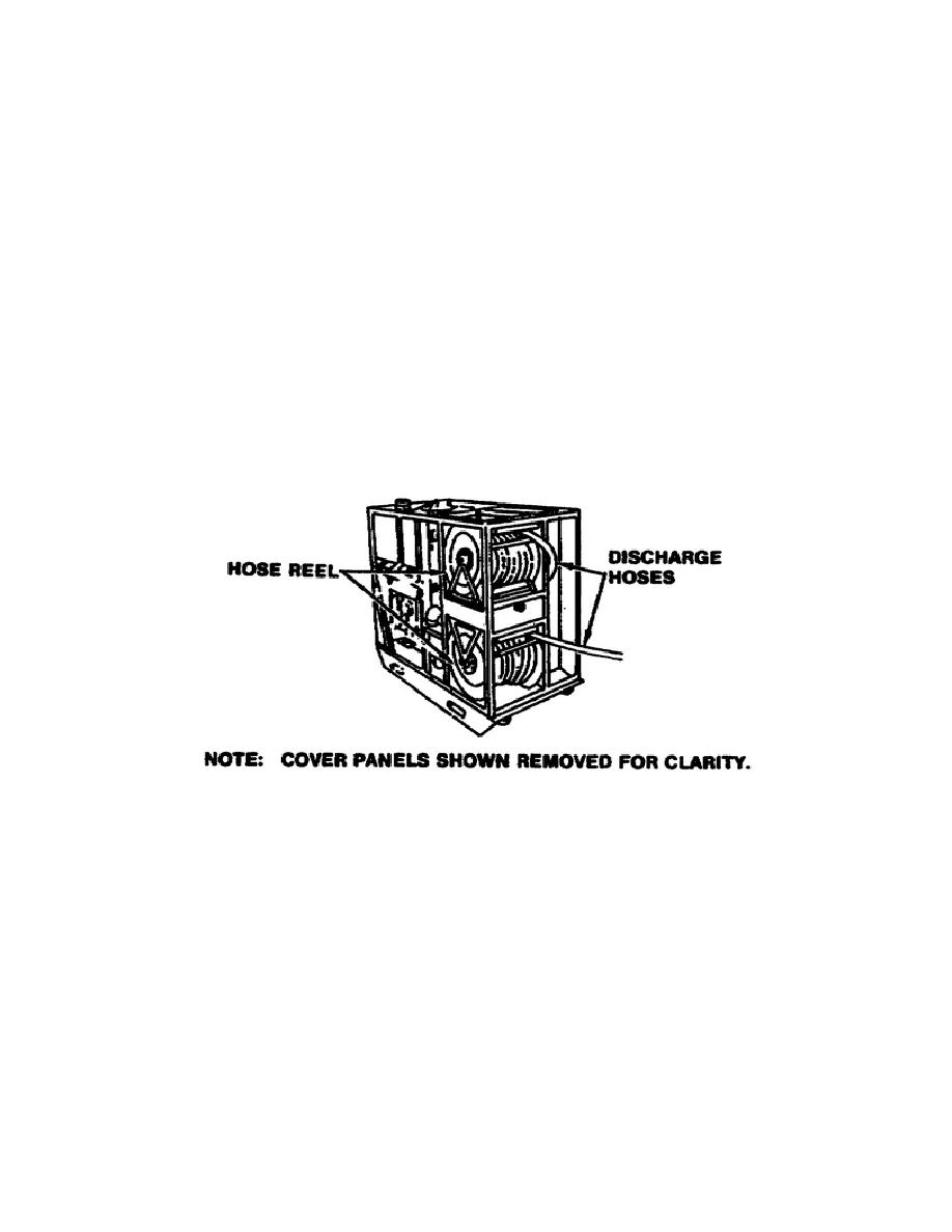
Discharge Hoses and Hose Reels
Two discharge hoses, with a female swivel coupling at each end, are installed on the hose reels. The
discharge hoses are 50 feet long. Each discharge hose terminates with hose couplings that connect to the
hose reel on one end and to a spray gun assembly on the other end. The discharge hoses are used to
discharge liquids from the pump unit assembly.
The hoses and hose reels are shown in Figure 4. A gun assembly and nozzles are used on the hoses.
Figure 4. Discharge hoses and reels.
Gun Assembly. The gun assembly is shown in Figure 5. The gun assembly consists of a gun handle, an
adapter, an extension pipe, gaskets and washers. The adapter connects the gum assembly to the
discharge hose. When the gun handle is in line over the ball valve and the extension pipe, the ball valve
is open. When the gun handle is rotated 90 degrees, the ball valve is closed.
Nozzles. In addition to the slurry nozzle, which is most often used with the gun assembly, there are two
nozzles which are used for fire fighting.
7

 Previous Page
