The tank houses a water pump and contains its working parts. The tank cover forms one side of the
pump. Screws fasten the cover so the tank. The pump drain hole is in the cover. The lubrication fitting
is fastened in the tank. It provides the means of greasing the shaft and the bearings inside the tank
housing. The breather allows excess grease and vapors to vent from the tank.
Suction Vacuum Gage and Tubing. The suction vacuum gage and tubing consist of plumbing
connections and a pointer indicating gage. This gage gives a visual indication of the vacuum developed
by the pump. The gage is scaled in 0 to 30 inches of mercury. This gage is shown in Figure 2.
Discharge Pressure Gage and Tubing. The discharge pressure gage and tubing consist of connections
and the discharge pressure gage. This gage gives a visual indication of the pressure developed by the
pump. The gage is scaled from 0 to 300 psi. This gage is shown in Figure 2.
Prime/Eductor Piping. The prime/eductor piping consists of the piping, elbow, bushing, eductor, and
street elbow. The prime-detergent piping connects into the pump-suction piping at the eductor. The
eductor is threaded on both ends. A ring, which acts as an orifice, is welded inside the eductor.
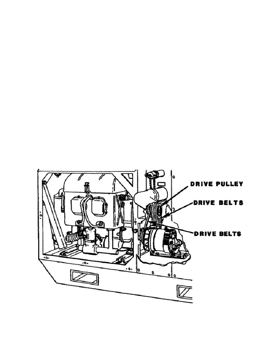
Drive Pulley. The four-groove drive pulley is turned by belts from the engine and transfers power to the
pump shaft (Figure 3).
Figure 3. Drive pulley.
6


 Previous Page
