7
10
92
275
30
90
30
32
100
GZ
64
1,000 cGyph
82
300 cGyph
100 cGyph
31
120
110
29
90
8
0
110
10 cGyph
10 cGyph
90
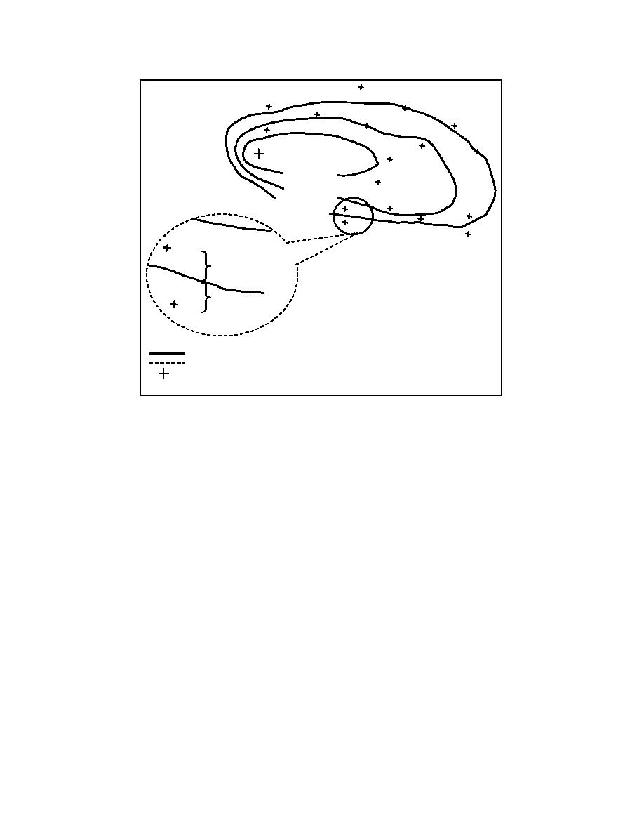
= Contour line
= Callout
GZ = Ground zero
Dose rates at H + 1
Figure 6-4. Construction of Dose Rate Contour Lines
plots the location, the time of the reading, and normalized dose rates on the radiological contamination
overlay. Points of equal dose rates are connected to give a series of contour lines by interpolating
between the plotted dose rates.
a. The 30-cGyph contour line in Figure 6-3 is estimated to be between the 20-cGyph reading and
the 40-cGyph reading. At the next set of readings, the 30-cGyph contour line is estimated to be closer to
the 35 cGyph than to the 10 cGyph. The 20-cGyph contour line is drawn through the 20-cGyph plot. At
the next set of readings, the 20-cGyph contour line is drawn between the 10-cGyph reading and the 20-
cGyph contour line. The plotter must use care and judgment in plotting these contours and must visualize
the probable general shape and direction of the pattern.
b. In addition, dose rate readings indicating possible hot spots must be carefully weighed. These
will appear as dose rates disproportionately higher than other readings in the immediate area. When such
readings are reported, a recheck in that area should be made; if confirmed, these hot spots should be
plotted and indicated clearly. The plotted contours may be extended or extrapolated to areas downwind in
which fallout has not arrived and may be extended to intersect with ground zero, if necessary, to complete
the fallout pattern. As more information is received, the pattern is altered accordingly and thus
maintained up to date. Figure 6-5 shows a typical plot that might be developed from survey data.
CM2306
6-7


 Previous Page
