The volume of the hopper-blender assembly is sufficient to allow quick addition of STB or other
decontaminants during the mixing process. A liquid level indicator attached to the side of the hopper-
blender assembly indicates the number of gallons of liquid in the tank. The indicator is scaled from 100
to 447 gallons.
Foot Valve
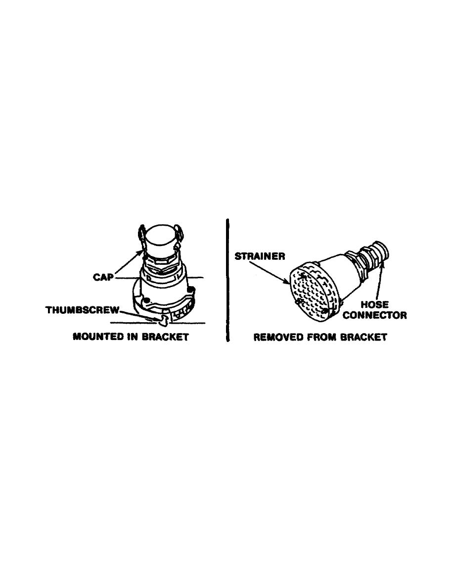
The foot valve (Figure 10) prevents solids from entering the suction hose when water is being pumped
into the tank from a natural source. The foot valve will prevent rocks and gravel from entering the
pump, but will not prevent fine sand or silt from entering. On one end, the foot valve has a strainer. On
the other, it has a quick-disconnect coupling half for attachment to the suction hose. When not in use, a
cap covers the quick-disconnect coupling and the foot valve is stowed in a bracket on the tank unit
assembly. A thumbscrew tightens and holds the foot valve in the bracket. The stowage location of the
foot valve is shown in Figure 8.
Figure 10. Foot valve.
Personnel Shower Assembly
The personnel shower assembly enables the M12A1 PDDA to be used to provide a shower facility for
personnel. It is packed partially dismantled in brackets on the tank unit. The personnel shower consists
of an assembly of six 34-inch lengths of pipe with necessary supports and connections. On the shower
pipes, four pairs of 5/32-inch diameter holes are drilled in each pipe. Water for showers can be pumped
from the tank unit or from an external source. The M2 water heater can be used to heat water for the
shower assembly.
13


 Previous Page
