NOTE
This is an example to demonstrate a procedure. In actual practice, the points will not likely
fall exactly on a straight line as in Figures 6-2 and 6-4. In actual practice, the best straight
line is fitted to the points.
A linear scale is superimposed on the graph as illustrated in Figure 6-4 to show the determination of
linear measurements. The linear scale is a set of measurement spaced at even intervals (in Figure 6-4,
the interval is 1/2 inch). Since the linear scale is used to develop a ratio, the actual position is of little
importance, however it is normally run along the left edge and bottom of the graph. The point where the
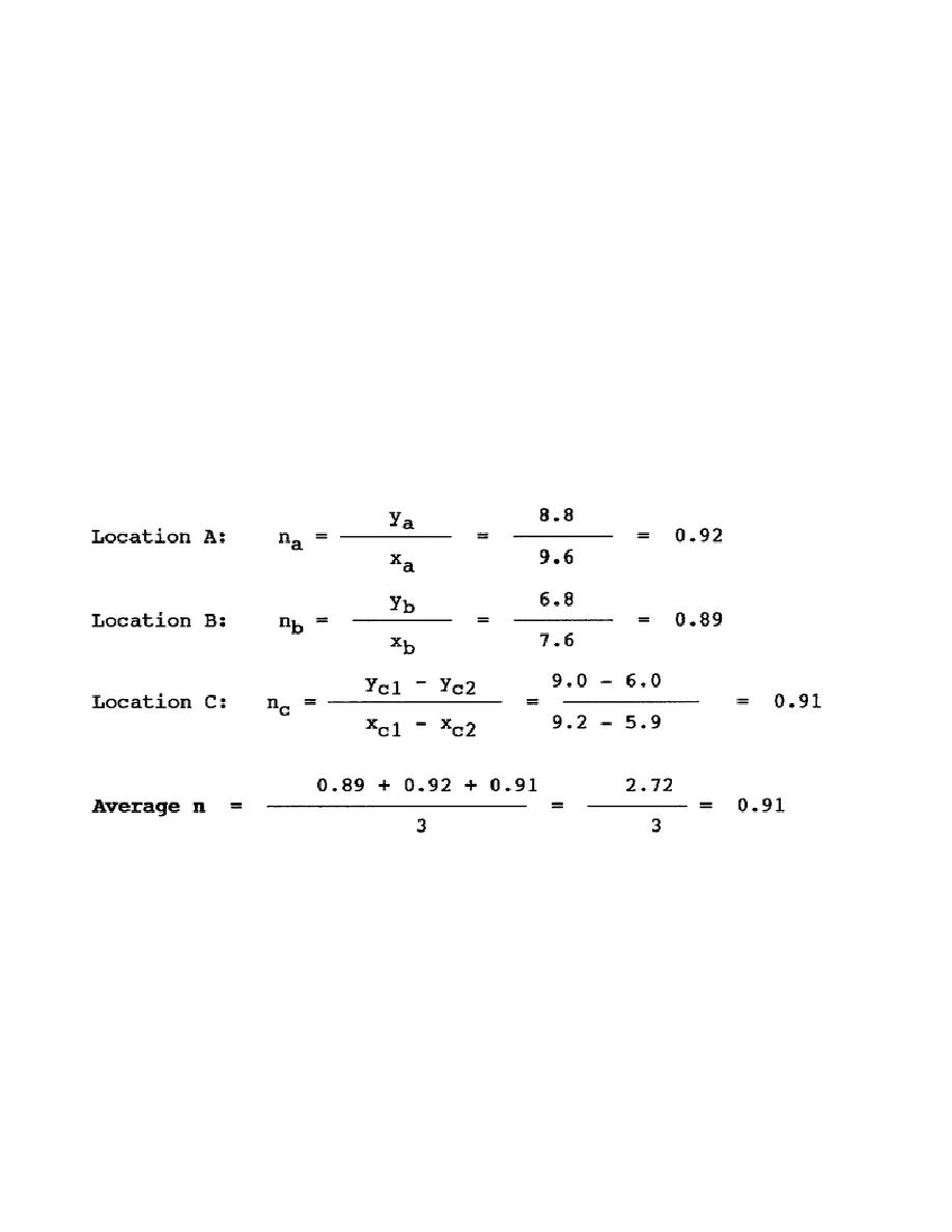
slope intersects the linear scale line is the linear measurement of the axis. The value of n may then be
determined for each location and an average n determined as shown below.
To obtain the ratio values for a slope that does not intersect the linear scale (location C), mark any two
points on the slope and mark them C1 and C2. Read across the graph from these points and take the
values from the linear scale along the y axis. These values then become YC1 and YC2. From points C1
and C2 on the slope, read down the graph to get the values xC1 and xC2. Insert these values as shown
below to get the average n.
Once the decay rate n is determined, the radiological reading may be normalized to H + 1 reading. This
reading is commonly referred to as the R1 reading. This is nothing more than determining
mathematically what the dose rate reading was at any given location one hour after the burst. Survey
teams and monitors enter an area and take readings at various times after the burst (H-hour). These
readings may be 15 minutes or 10 hours
CM2308
6-6


 Previous Page
