Lesson 3/Learning Event 1
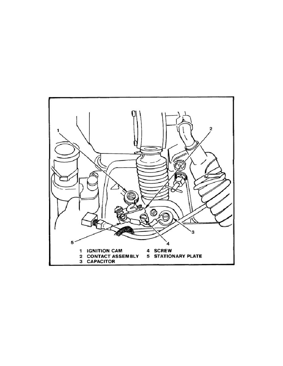
Step 3. Remove the two screws which hold the contact assembly in place and remove the
contact assembly.
Step 4.
Clean the contact assembly with filtered, compressed air.
Step 5.
Inspect the contacts for pitted, burned, misaligned, or worn surfaces.
Step 6.
Inspect the cam follower for cracks, breaks, or wear.
FIGURE 20. CONTACT ASSEMBLY AND CAPACITOR.
for continuity between the terminal and the capacitor case or mounting lug. No continuity should
be indicated. If continuity is indicated, discard the capacitor. Check the lead for damage or a
broken terminal end.
50


 Previous Page
